Self Balancing Robot V1 (Prototype)
The foundational proof-of-concept for a Brushed DC self-balancing robot.
Project Synopsis
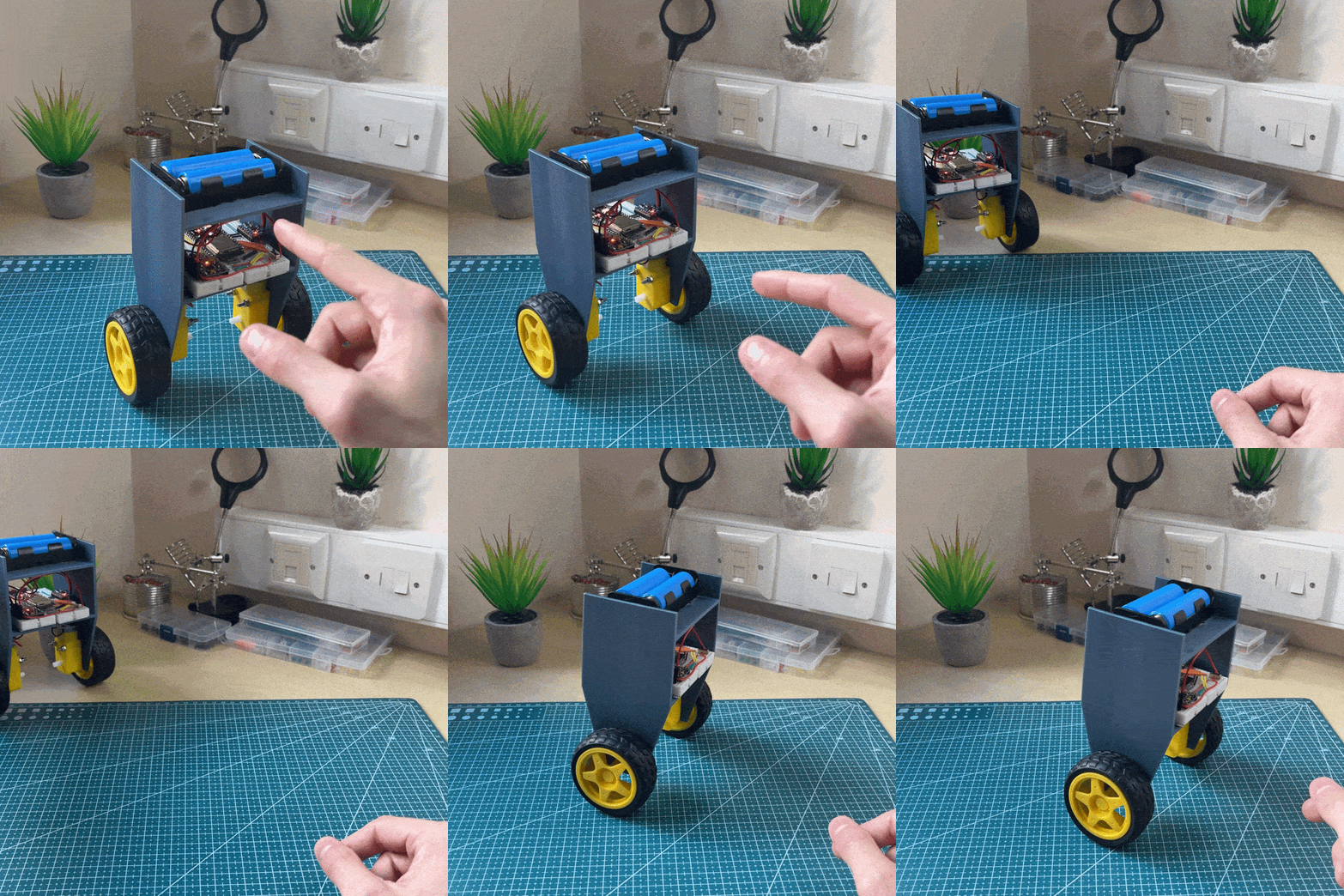
The V1 platform serves as the foundational hardware proof-of-concept for a Brushed DC Self-Balancing Robot.
Developed entirely within the Arduino IDE toolchain, this initial prototype focused on establishing the real-time control loops and verifying the ability to balance despite the inherent nonlinearities of encoderless Brushed DC Motors.
Core Engineering Skills Acquired
Configured memory partitions, clock limits, and hardware I2C transmission on the ESP32-S3 (N16R8) microcontroller.
Integrated a buck converter to regulate the voltage rails, ensuring high current motors do not starve MCU logic.
Implemented a discrete multivariable Kalman Filter algorithm to fuse noisy sensor data and resolve gyroscopic drift.
Designed an independent PID controller to map vertical setpoint error into discrete PWM duty cycles for motor actuation.
Mechanical Design
01 // Monolithic CAD Model
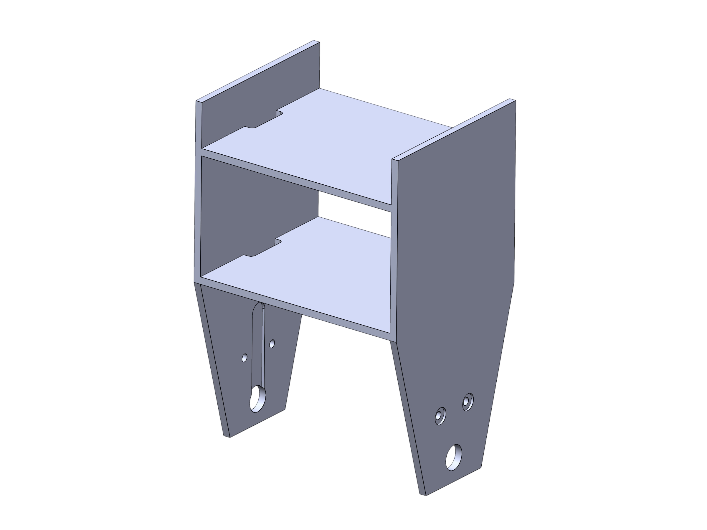
The chassis, which incorporates inset motor mounts and two decks, was modelled as a single integrated part within SolidWorks for prototype simplicity.
02 // FDM Fabrication
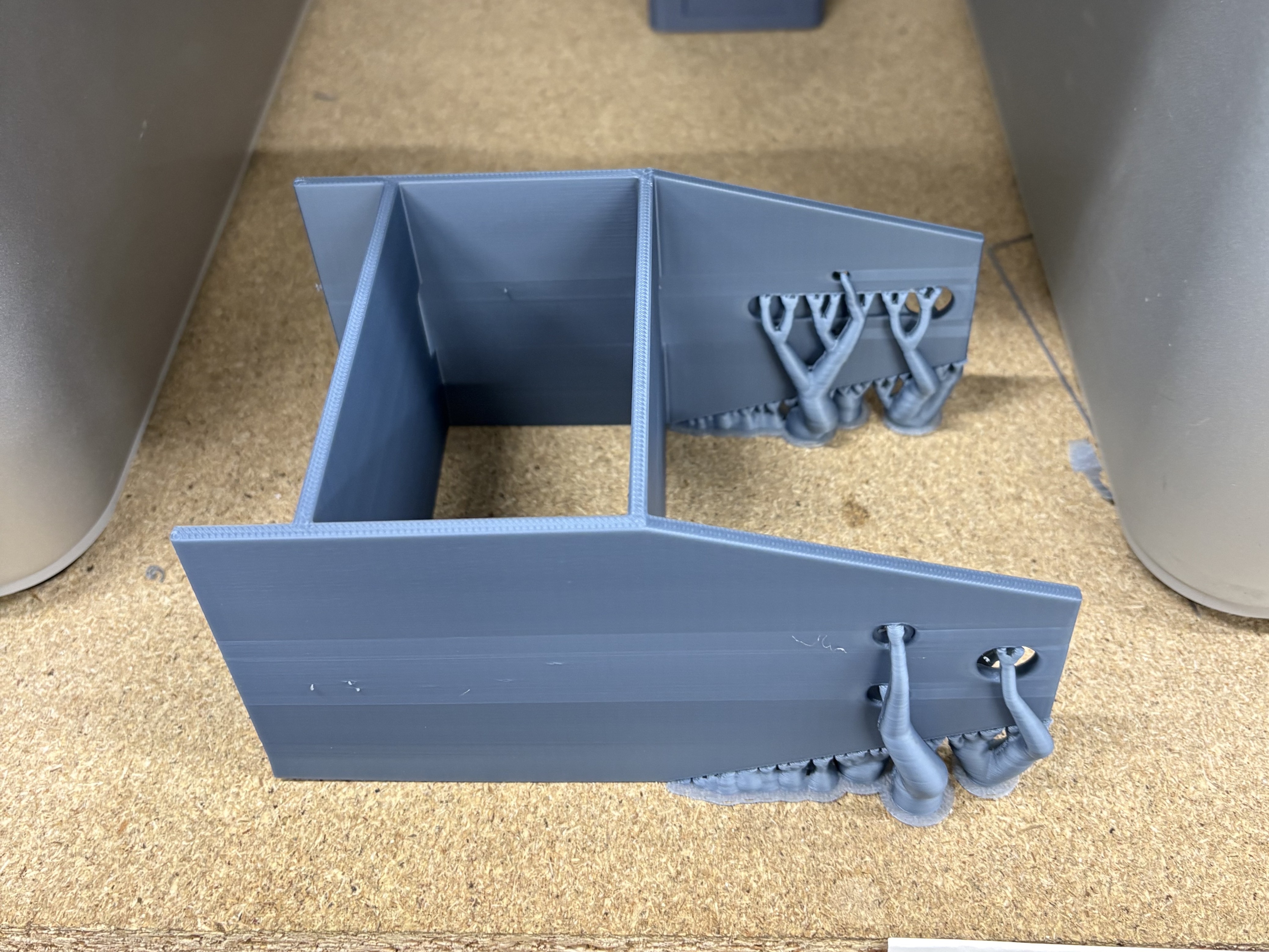
The integrated chassis was fabricated using fused deposition modelling (FDM) 3D printing, and printed in Standard PLA.
03 // Component Placement
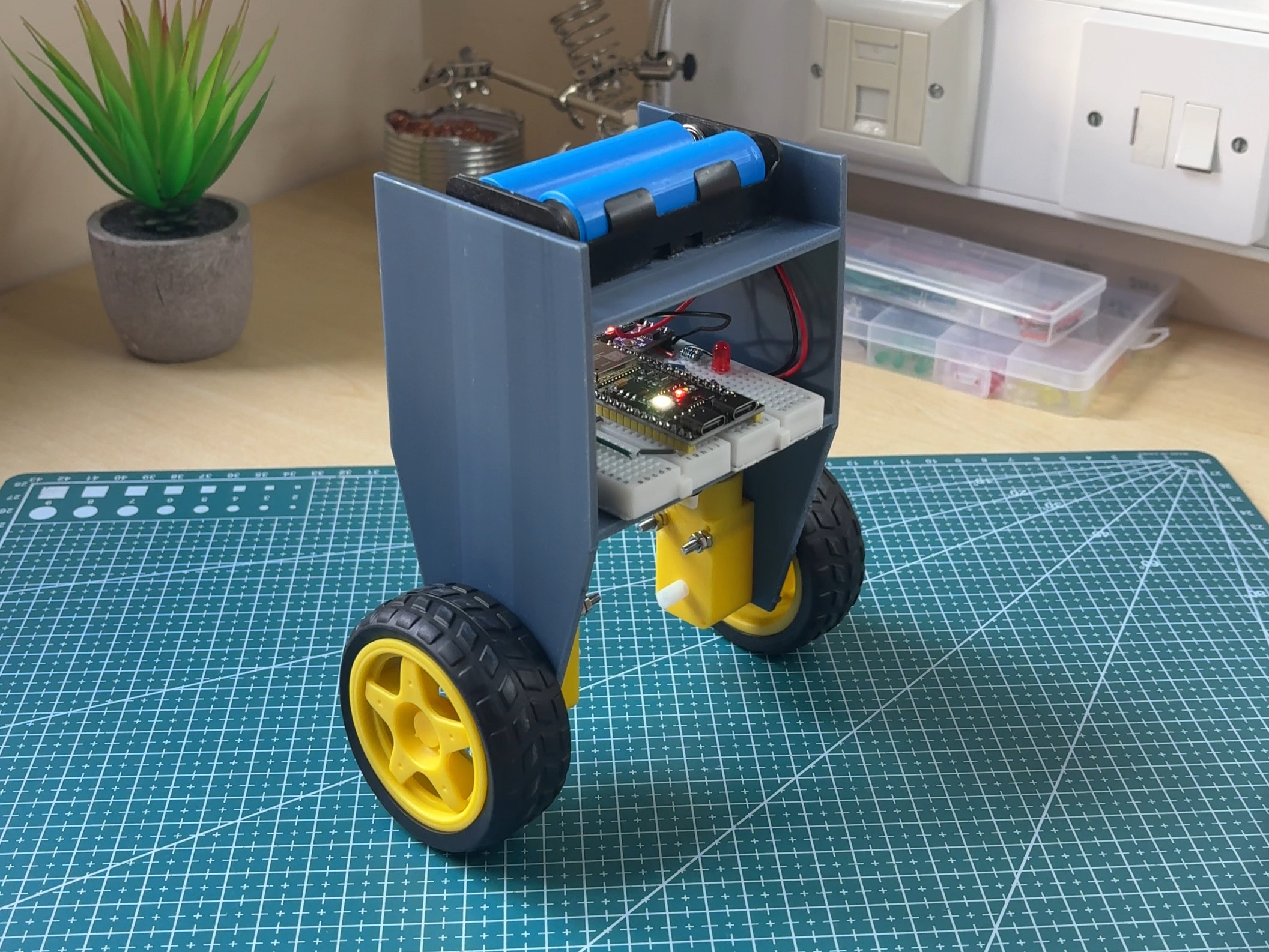
The heaviest component (2S LiPo battery) was intentionally placed on the highest deck. This increases the system's total moment of inertia (I), minimizing angular acceleration (α = τ / I) to grant the PID controller more recovery time to counteract rapid tilt changes.
Electrical Hardware
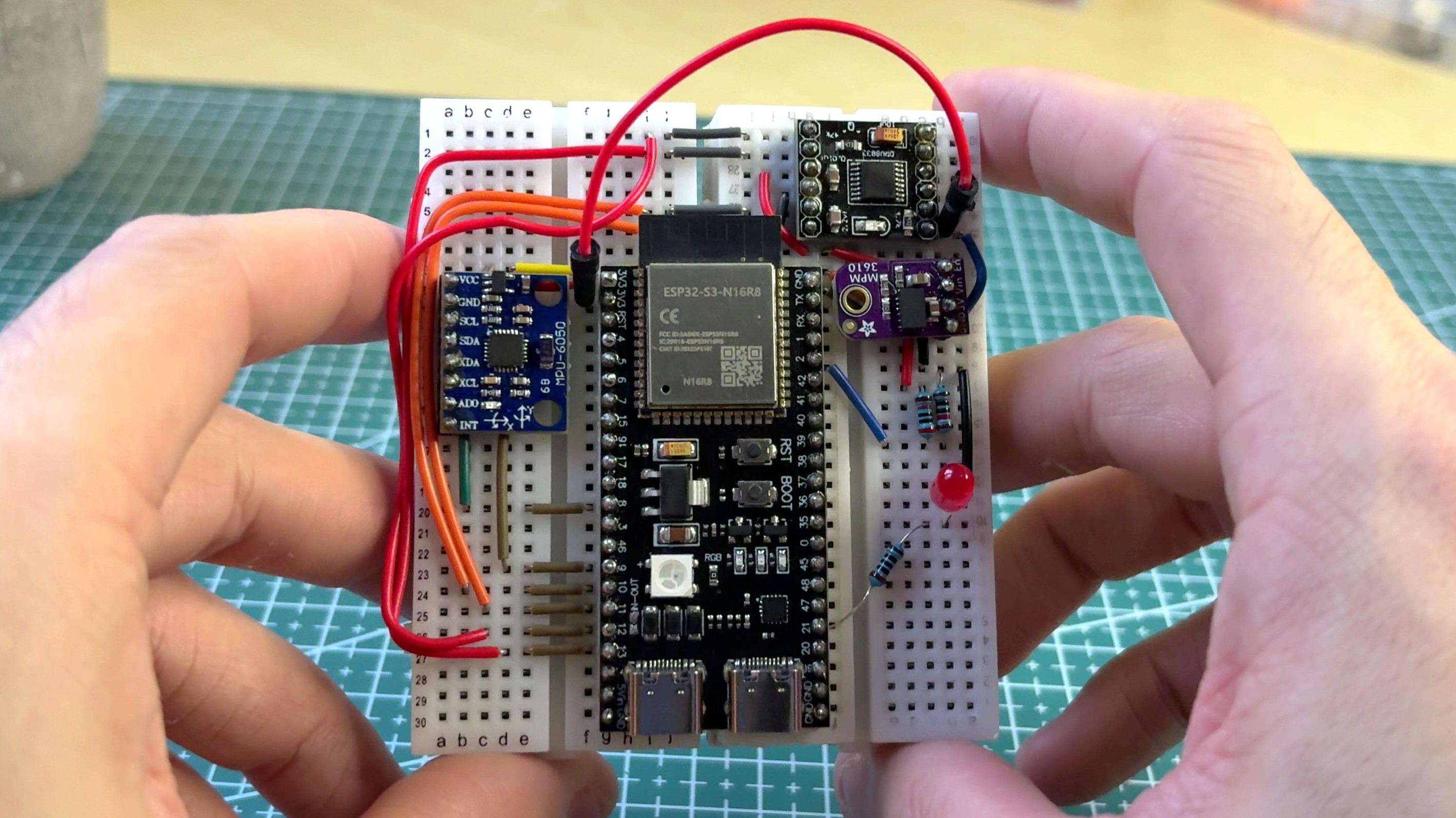
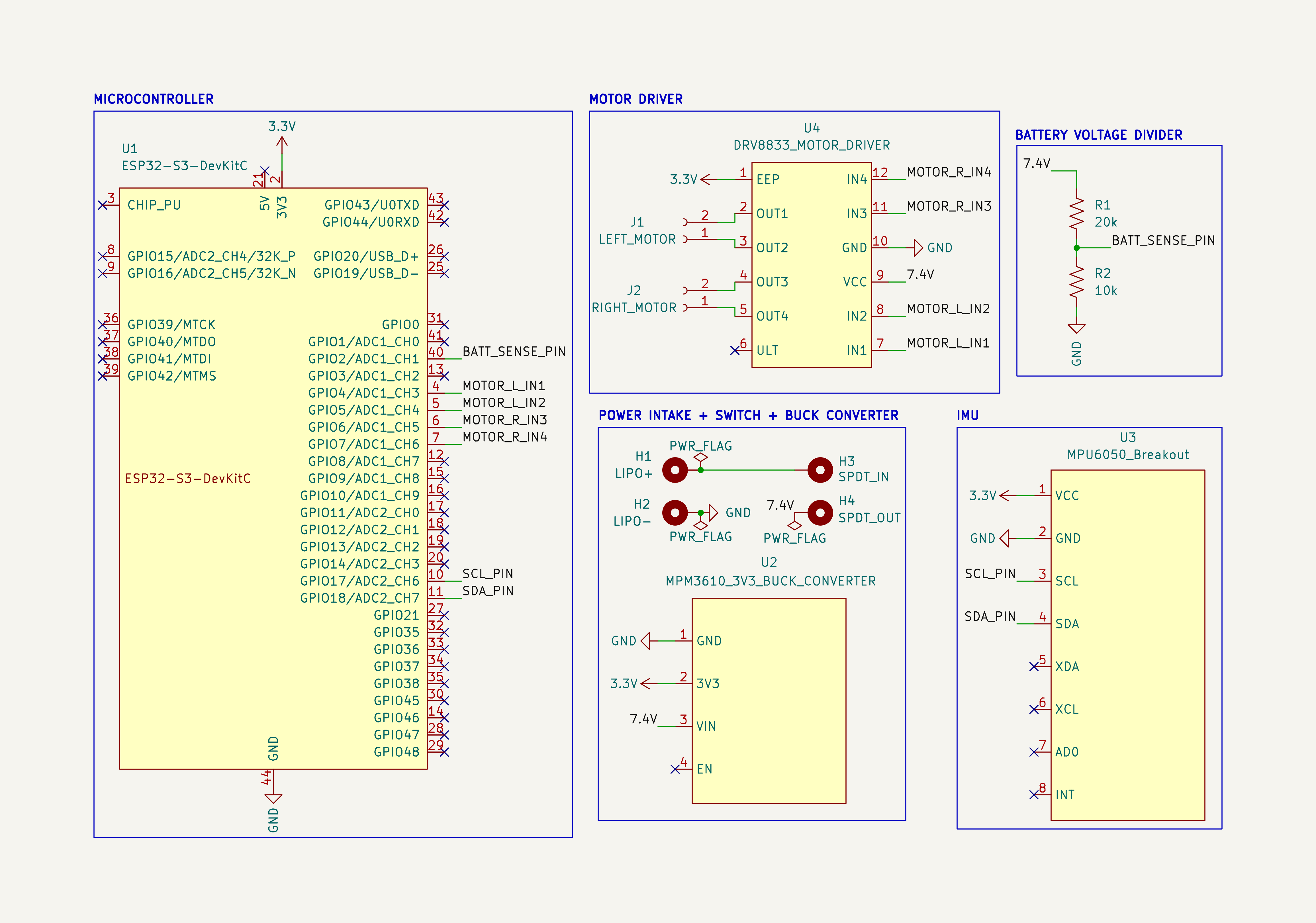
The electrical network was constructed across two half-sized breadboards, mated together with their power rails removed:
Circuit Architecture Highlights
The 2S LiPo Battery delivers a raw 7.4V voltage directly to the DRV8833 motor driver pins. Concurrently, the MPM3610 step-down buck converter drops that shifting battery voltage down to 3.3V to drive the ESP32-S3 and IMU.
The MPU6050 communicates with the ESP32-S3 over a dedicated hardware I2C bus operating at 400kHz clock speed to ensure low latency data retrieval.
Firmware Architecture
The firmware executes on a non-blocking timing loop within the Arduino framework to ensure fixed-interval control updates.
State Estimation via a Custom Kalman Filter
The Challenge
Raw IMU accelerometer readings are highly susceptible to high-frequency noise from chassis vibrations, while gyroscope readings experience cumulative, low-frequency sensor drift over time.
The Solution
Developed a discrete, two-state Kalman filter that fuses the gyroscope and accelerometer data and dynamically injects process noise (Q) and measurement noise (R) to model real-world uncertainties.
The Outcome
Isolates the true tilt angle (θ) by eliminating noise, providing clean state estimation for the robot controller.
void KalmanFilter::predict(float *gyro) {
    // A Priori State Estimate with Gyroscope Readings ( New_Angle = Old_Angle + (Angular_Velocity * dt_sec) )
    roll  += gyro[0] * RAD_TO_DEG * dt_sec;
    pitch += gyro[1] * RAD_TO_DEG * dt_sec;

    // Uncertainty Grows (To account for gyroscopic drift, inject Process Noise Q into the Covariance matrix)
    Sigma[0] += Q[0] * dt_sec;
    Sigma[3] += Q[1] * dt_sec;
}
void KalmanFilter::measurement_task(float *accel) {
    // Calculate True Measured Tilt with Accelerometer Readings
    m_roll  = atan2(accel[1],  sqrt(sqr(accel[0]) + sqr(accel[2]))) * RAD_TO_DEG;
    m_pitch = atan2(-accel[0], sqrt(sqr(accel[1]) + sqr(accel[2]))) * RAD_TO_DEG;

    // Compute Innovation Covariance S (Fuse initial uncertainty with Accelerometer measurement Noise R)
    float S0 = Sigma[0] + R[0];
    float S1 = Sigma[1];
    float S2 = Sigma[2];
    float S3 = Sigma[3] + R[1];

    // Compute Kalman Gains (($K = \Sigma * S^(-1)$))
    k_det = 1.0f / (S0 * S3 - S1 * S2);

    k_gain[0] = (Sigma[0] * S3 - Sigma[1] * S2) * k_det;
    k_gain[1] = (Sigma[1] * S0 - Sigma[0] * S1) * k_det;
    k_gain[2] = (Sigma[2] * S3 - Sigma[3] * S2) * k_det;
    k_gain[3] = (Sigma[3] * S0 - Sigma[2] * S1) * k_det;

    // Calculate the Error Between the Accelerometer Reading and the A Priori Estimate
    float r_error = m_roll - roll;
    float p_error = m_pitch - pitch;

    // Update the Roll and Pitch with Kalman Gains
    roll  += (k_gain[0] * r_error) + (k_gain[1] * p_error);
    pitch += (k_gain[2] * r_error) + (k_gain[3] * p_error);

    // Update Error Covariance Matrix (A Posteriori Estimation)
    float s0 = Sigma[0], s1 = Sigma[1], s2 = Sigma[2], s3 = Sigma[3];
    Sigma[0] = (1.0f - k_gain[0]) * s0 - k_gain[1] * s2;
    Sigma[1] = (1.0f - k_gain[0]) * s1 - k_gain[1] * s3;
    Sigma[2] = -k_gain[2] * s0 + (1.0f - k_gain[3]) * s2;
    Sigma[3] = -k_gain[2] * s1 + (1.0f - k_gain[3]) * s3;

    // Enforce Matrix Symmetry (If any rounding errors accumulate)
    float relationship_avg = (Sigma[1] + Sigma[2]) * 0.5f;
    Sigma[1] = Sigma[2] = relationship_avg;
}
PID Control Loop Implementation
The Challenge
A self-balancing robot (similar to an inverted pendulum) is inherently unstable and falls due to gravity. Simple binary motor commands fail to maintain equilibrium and cause violent over-corrections.
The Solution
Instead of binary motor outputs, a PID controller breaks the motor output into three scaled adjustments:
▪Proportional (P): Scales output power proportionally to tilt amount.
▪Integral (I): Tracks past errors over time to eliminate lingering tilts.
▪Derivative (D): Applies a low-pass filter to the future rate of change of error, suppressing over-corrections.
The Outcome
Optimal tuning of the PID parameters generates motor outputs that reliably maintain vertical equilibrium.
float PID::control(float cur_angle, float max)
{
    error = setpoint - cur_angle;

    // DERIVATIVE: Compute raw rate of error change and apply an 80/20 discrete low-pass filter
    float raw_derivative = (error - previous_error) / dt;
    derivative = (0.80f * previous_derivative) + (0.2f * raw_derivative);

    previous_error = error;
    previous_derivative = derivative;

    // INTEGRAL: Constrained to prevent integral windup from saturating the motor capacity
    integral = constrain((integral + (error * dt)), -1.20f, 1.20f);

    // Output the PID corrected motor output
    out = (kp * error) + (ki * integral) + (kd * derivative);
    return constrain(out, -max, max);
}
Evaluation & Moving Forward
While the V1 prototype successfully validated my core stability algorithms, it highlighted critical structural, electrical, and architectural bottlenecks. The roadmap below tracks these failure modes alongside their engineered V2 solutions:
Repository, Assets, and BOM
Bill of Materials (BOM)
To establish a clear development history, all component selections and unit costs are logged below:
2x 3.7V LiPo Battery ↗
High-discharge power source necessary to counter immediate motor torque spikes.
1x 2 Slots LiPo Battery Holder ↗
Secure the batteries in a 2S configuration for a raw 7.4V.
1x MPM3610 3V3 ↗
Ultra-compact 21V, 1.2A step-down module providing clean 3.3V logic power.
1x ESP32-S3 (N16R8) ↗
240MHz dual-core processing power with ample flash space for control calculations.
1x MPU6050 GY-521 ↗
3-axis accelerometer and 3-axis gyroscope combined on a single I2C bus.
1x DRV8833 ↗
Dual MOSFET H-Bridge supporting low-saturation resistance and slow-decay active braking routines.
2x BDC TT Geared Motors with Wheels ↗
Budget-friendly brushed DC motors with wheels.
Custom 3D Printed Chassis (~91g PLA)
Custom structural frame designed to mount the TT motors, battery holder, and breadboard.
2x Half-size Breadboards, Assorted Jumper Wires
Rapid prototyping framework allowing quick hardware loop signal adjustments.
Repository Information
All firmware and hardware files are completely open-source:
Firmware
Directory containing the primary balancing_robot.ino logic core, alongside custom Kalman Filtering and PID Control Algorithm header files
Hardware
Production asset directory containing original SolidWorks CAD source models (.SLDPRT) and slice configurations (.3mf) ready for manufacturing.
View The Repository
All resources and dependencies are can be downloaded directly from the open-source branch master directory tree.